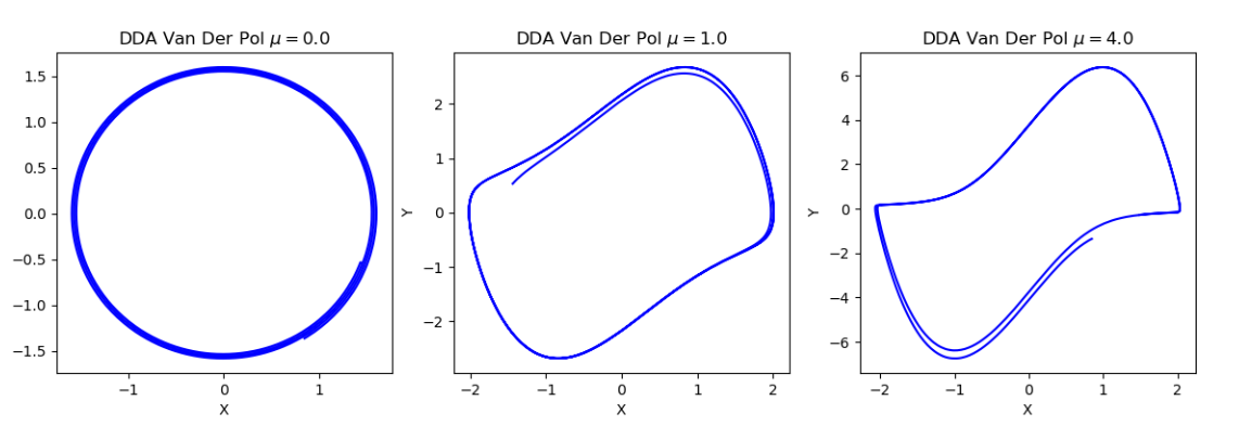
270 DDA solver for van der Pol oscillator
270 : DDA solver for van der Pol oscillator
- Author: Adonai Cruz
- Description: Digital differential analyzer (DDA) solver for the van der Pol oscillator using posit (16,1)
- GitHub repository
- Clock: 0 Hz
How it works
The DDA core expects to receive via SPI port the parameter for the van der Pol oscillator encoded in posit (16,1) padded with 2 zero bytes to compose a 32-bit word. When an SPI message is started by the master (SPI CS pin low) the integrators are clocked and solutions for both state variables, X and Y, are transmitted back serially via SPI as a single 32-bit word for each time step with the 16 bits MSB encoding X and the 16 bits 16 bits LSB encoding Y. Simulation can be stopped by stopping communication via SPI.
How to test
In order to test chip reset the chip (RST_N active low) and start a duplex SPI communication transmitting 32-bit word with the van der Pol parameter $\mu$ encoded in posit (16,1) using the 16 bits LSB of the 32-bit word (padded with zeros). A controller software to interface with the chip via FTDI FT232H using SPI is available at https://github.com/adonairc/tt07-dda-van-der-pol

External hardware
This projects uses the top row pins of PMOD for SPI:
uio[0] - CS
uio[1] - MOSI
uio[2] - MISO
uio[3] - SCK
IO
| # | Input | Output | Bidirectional |
|---|---|---|---|
| 0 | SPI CS | ||
| 1 | SPI MOSI | ||
| 2 | SPI MISO | ||
| 3 | SPI CLK | ||
| 4 | |||
| 5 | |||
| 6 | |||
| 7 |